Leading-Edge Digital Circuits
Our instruments are using leading-edge ultra high-speed analog-to-digital converters with sample rates of several GS/s (Gigasamples per second), most modern Field Programmable Gate Arrays (FPGAs) which use logic cells and calculation blocks for the emulation of several thousand EMI receivers in parallel.
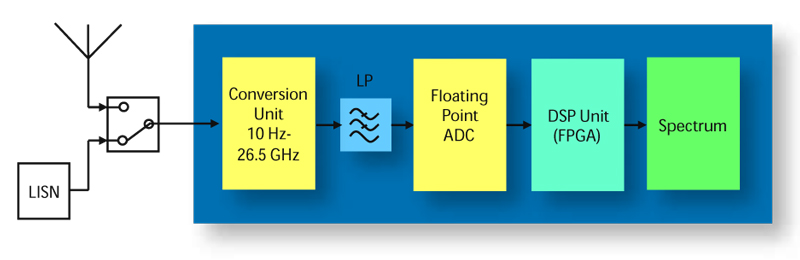
In Fig. 38 the block diagram of a TDEMI Measurement System is shown using the example of the TDEMI 26G. The received EMI signal of the frequency range from 10 Hz to 1.1 GHz is digitized with a floating-point ADC. The frequency range above 1.1 GHz is down-converted with an ultra-broadband multi-stage down-converter unit which exhibits a real-time analysis bandwidth of 162.5 MHz. Afterwards the signal is digitized in the baseband.
The emulation of up to 4000 EMI receivers in parallel based on a Fast Fourier Transform (FFT) filterbank is performed by FPGAs. These FPGAs have a computational power of more than 20 standard personal computers. This leading-edge technology allows to speed up the measurements performed by the TDEMI by several orders of magnitude in comparison to traditional superheterodyne receivers. Fully gapless real-time analysis is possible within frequency bands of 162.5 MHz for the first time.
The simplified block diagram of such a digital implementation of several thousand receivers is shown in Fig. 39.
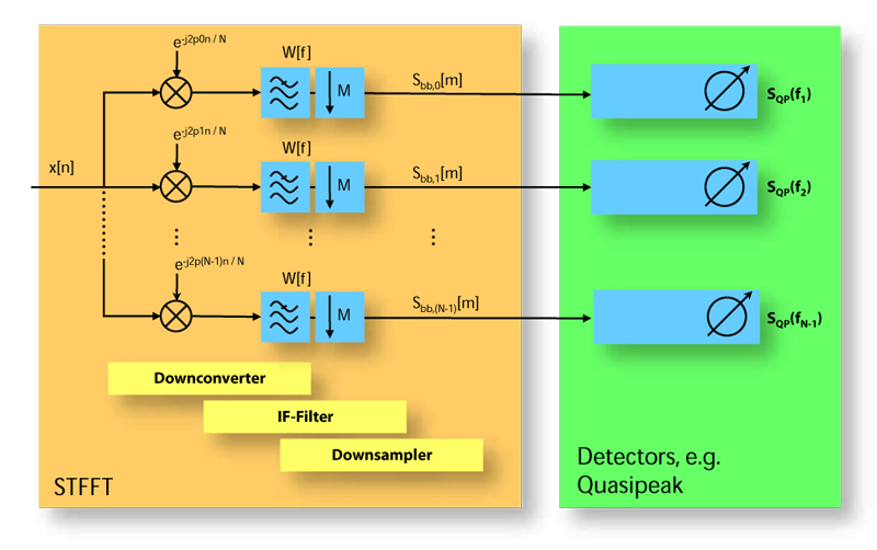
In general an EMI receiver consists of a down-converter, an IF filter and a detector for weighting, e.g. quasi-peak. The use of a short-term FFT (STFFT) based filter bank allows to perform a down-conversion of a large set of frequencies with equidistant step-size. A highly parallel implementation of detectors by a digital bank of filters allow the simultaneous calculation at a vast number of frequencies.
The floating point ADC unit that performs the digitization of the EMI signal consists of three 8-bit ADCs with a sampling rate up to 3 GS/s. The scaling of the three branches is in logarithmic scale to digitize pulses and other transient signals with a high dynamic range, which corresponds to the dynamic range of a 20 bit ADC for pulses. These huge dynamic range is required for the digitization of pulses according to CISPR 16-1-1 that are necessary for calibration of the instrument. Such pulses can have an amplitude of several Volts, while the instrument must be able to provide simultaneously a very high sensitivity for signals of few μV which are close to the noise floor.